Wilhelm Jerger
1907 : Inventor of the toy game
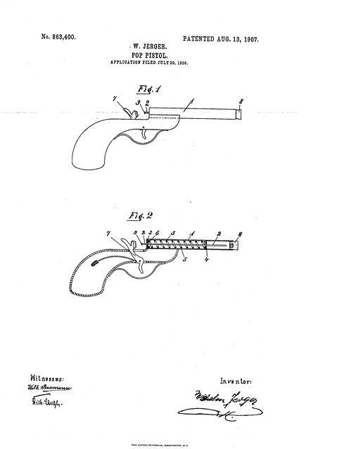
POP PISTOL - PLOOP

DESCRIPTION (Le texte OCR peut contenir des erreurs.)
(No Model.)
WILHELM JERGER. CLOCK WINDING MECHANISM.
Patented June 23, 1896
UNITED STATES PATENT OFFICE.
WILHELM JERGER, OF NIEDERESCHACH, GERMANY.
CLOCK-WINDING MECHANISM.
SPECIFICATION forming part of Letters Patent No. 562,539, dated June 23, 1896.
Application filed December 3, 1895. Serial No. 570,915. (No model.) Patented in France $eptember 7, 1893, No. 232,681; in Germany December 7, 1893, No. 77,766; in Austria-Hungary March 14, 1894, No. 51,451 and No. 81,300, and in England July 10, 1894,110. 13,360.
T 0 aZZ whmn it may concern.-
Be it known that I, WILHELM JERGER, a subject of the Emperor of Germany, residing at Niedereschach, in the Grand Duchy of Baden, Germany, have invented new and useful Improvements in Clock Mechanism, (for which I have obtained patents in France, No. 232,681, dated September 7, 1893; in Germany, No. 77,766, dated December 7, 1893; in Austria-Hungary, No. 51,451 and No. 81,300, dated March 14, 1894:, and in England, No. 13,360, dated July 10, 1894,) of which the following is a specification.
In the construction of clocks and watches, especially of that class which are adapted to run for one week or more with but one winding, various devices and arrangements have been employed to overcome the inequalities of pressure exerted by the mainspring of the timepiece, the pressure of the spring being greatest when under full tension, and at its minimum point when the mechanism is nearly run down.
Among other improvements an attempt has been made to provide a train of wheels wherein the escapement-wheel is acted upon by a small spring secured to the shaft of said wheel, so that same shall be automatically wound up by the mainspring at alternate periods. The defective points of this system are obviated by my improvement, as will be readily understood by reference to the ac companying drawings and description of same.
Figure 1 is a front view of a clock mechanism provided with my improvement, and Fig. 2 an edge or side view of same. Figs. 3, 4, 5, 6, and 7 are detail views for the better understanding of my invention.
In order that my improvements may be clearly shown and therefore better understood, they are represented in Figs. 1 and 2 at the top of a small train of clock-gearing, but it is evident that the said improvements may be employed in any other suitable construction of clockwork or escapement.
In the clock mechanism as illustrated in the accompanying drawings, power is imparted to the main shaft by a spring A and from said shaft through an ordinary ratchet-wheel as shown at f f in Figs. 2, 5, and 6.a and gear-wheel a to the pinion B of a shaft B, on which is a cog-wheel b, engaging a pinion O of a shaft (1, upon which a spring D is mounted in such way that in a determined period, for instance, after each minute, it w1ll be wound up, and thus be made to drive the wheel cl, which is loosely fitted on the same shaft and adapted to drive the pinion d on the shaft of which is a wheel d for engaging a pinion c of a shaft 6 to which the escapement wheel E is also secured.
The spring D has its outer end securely connected with the wheel clbya pin 61 (see Fig. 3) and its inner end with the shaft d, so as to exert a medium tension. The train from a to c is thus under the action of the mainspring A and the train cl to E is under the influence of the small spring D. The wheel 0 imparts motion by means of pinion f and its shaft to the disk or wheel f, which is provided at opposite sides thereof, and at one hundred and eighty degrees apart, with pins, These pins are arranged in two different planes, so as to successively act against the two halfcylinders g 9, (see Fig. 7,) and thus temporarily arrest the action of the mainspring A.
The pin f cooperates with the part g and the pin f with g when the wheel f has made a half-revolution under the pressure of the mainspring. In order to make the movement uniform, the wheel f in its sudden motion is adapted to drive a small fiy-wheel h", which is mounted on a shaft carrying a pinion h, which the said wheel f is made to engage. The escapement-wheel E is connected with the balance mechanism by any of the known escapement devices,here the hook of Clement.
It will be understood that the spring D,tending to unwind itself, will turn the wheel at,
connected therewith, in the direction of the arrow, (see Fig. 3,) so that by means of the wheels d 01 and e the escapement-Wheel E and balance-wheel h are operated in the well-known manner. During the rotation of the springD its tension is of course decreased. The power of the mainspring A, acting on the train a, a 17, b, and O, is arrested during the motion because its last Wheel 0 with its shaft (Z remains stationary. The wheel f, being connected with the spring D, is arrested by the pin f coming in contact with the cylinder 9. Through the wheels d d driven by the spring D, the cylinders g g are moved forward until the pin f slides off of the half-cylinder g, Fig. 5, and thus frees the wheel f, which movement causes the spring Ato immediately ,act on the train of gearing and causes, through wheel 0, the shaft. cl to turn in the direction of the arrow (see Fig. 3) until the pin f strikes against the half-cylinder g, thereby causing the train between the wheel 61 and the Wheel a to be again arrested. During the revolution of the shaft cl the spring D is again wound up to the extent it had previously run down by the action of the escapementwheel. Now when the half-cylinders have turned so far that the pin f slides away from the half-cylinder g the action above described is repeated again. Thus the wheels of the train from the wheel a to the wheel cl make their revolutions in a greater length of time, while the wheels from d to E perform their ordinary motion which is controlled by the balance h. The jumping motion is transferred to the inner shaft t" and the hands connected therewith by means of the wheel i, the said shaft being provided with a minutehand 6 The hour-hand is moved by the ordinary transmission.
The escapement-wheel E has-a period of rest, and a period of motion is adjusted, so that the winding up of the wheel (1 shall be in the former period, and thus a decrease of tension of the spring D is prevented during the said period.
As shown in the drawings, the small spring D is not-attached to the shaft of the escape ment-wheel, but upon the shaft d, which is in front of the escapement-wheel. The advantage of this arrangement is that the winding up of the spring D is only necessary after repeated revolutions of the escapementwheel.
In order to insure correct timekeeping for any length of time, care should be taken never to let the spring D run down to any great eX- tent. In fact it is better to have said spring always under tension of the same number of windings, t'. 6., the train should be wound up now and then to the extent it has unwound since the last winding. Thus when the mainsprin A has run down to its limit the spring D should not act any further upon escapement-wheel E, because otherwise the spring D would run down completely. To the end, therefore, to prevent further movement of the mechanism after the mainspring has run down, an arm d is secured to the sleeve d (see Figs. 2, 3, and 4) and the wheel d provided with a projecting pin d, which engaging the arm 61 looks the parts together and prevents further act-ion of the spring D.
The position of the arm 61 must of course be such that the pin d can touch it only after the disengagement of one of the pins f and the completion of its revolution.
In winding up the springA the power necessary produces a reaction of the'train, so that the turning of the wheel d on the shaft cl in an opposite direction might occur, which would mean the turning of the spring D in opposite sense. Now to prevent this backward movement, a second pin (Z of same length as d is made to project outward from wheel (1, so that the arm (1 shall play between the two projecting pins during the ordinary movement of the mechanism, but without touching either projection. When the wheel cl, however, receives an impulse from the backward motion, by winding up the mainspring, the shaft 01 and arm 61 have a tendency to turn in an opposite direction. to
their ordinary motion, which brings the arm d in contact with the pin (Z and such motion is thereby prevented.
The arrangement of the arm (Z playing only between the pins d and d prevents the running down of the spring D any farther than the limit determined by these pins by which it is always kept at a uniform tension, and thus a decrease in same is rendered impossible.
Having thus fully described my invention as well as the operation of same, what Iclaim as new, and desire to secure by LettersPatout, is
1. The combination in a clock-movement provided with a mainspring, of an equalizingspring, the shaft of which is connected with the shaft of the mainspring, and the shaft of the escapement-wheel, by separate systems of intermediate gearing, the system connecting with the escapement-wheel, embracing the wheel f, having pins f and f as described, and the cylinders g g, adapted to be engaged by the pins f and f substantially as described and for the purpose set forth.
2. In a clock mechanism, the combination of a mainspring, an equalizing-spring having an independent shaft connected with the mainspring-shaft, and the escapement-wheel shaft by separate trains of gearing, the cylinders g g and wheel f having pins f and f for engaging said cylinders as described, with the sleeve d having an arm (Z and the wheel d provided with a projecting pin d", substantially as described and for the purpose specified.
3. In clock mechanism, the combination of a mainspring and equalizingspring, the
shaft of the latter connected by separatetrains of gearing with the mainspring-shaft and escapement-wheel shaft, the wheel 1 and pins f f and the cylinders g g, with the wheel'd having pins (1, (Z and the sleeve d" and pin (1 substantially as described.
In testimony whereof I have hereunto signed my name in the presence of two subscribing witnesses.
l/VILIIELM JERGER. lVit-n esses CARL SoHo'rzKY, GUSTAV BiiLLnsBAon.
ORIGINAL SOURCE GOOGLE PATENTS ARCHIVE
http://www.google.com/patents/US562539